


1. Introduction
This report documents the findings of the fire resistance test of an electrical wiring system in accordance with appendix A and B of AS/NZS 3013:2005 and AS 1530.4:2014. The testing was done on 5 October 2021.
Warringtonfire performed the test at the request of the test sponsor listed in Table 1.
Table 1 Test sponsor details
| Test sponsor | Address |
|---|---|
| TransTech Electronic Controls Pty Ltd | Unit 2/48 Dellamarta Road Wangara WA 6065 Australia |
2. Test details
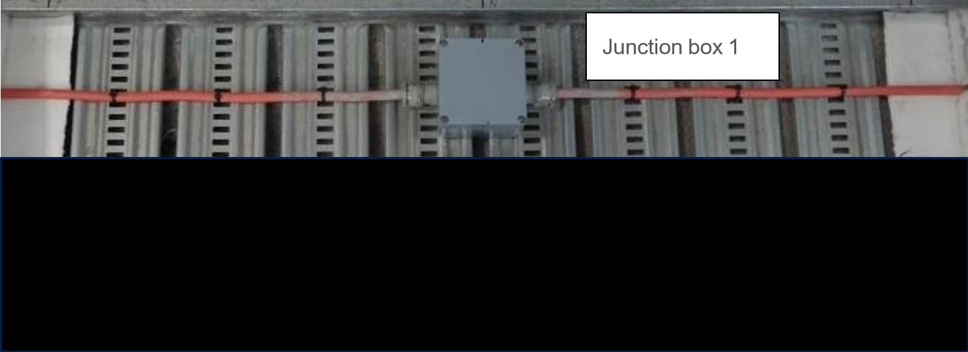
The junction box was positioned in the cable tray – as shown in Figure 1. Two junction boxes were tested in one cable tray. The results for junction box 1 are presented in this report.
The cable tray was made of 472 mm wide × 85 mm high × 0.7 mm thick steel. It was supported at the centre with a 42 mm × 42 mm × 2.5 mm thick U-steel section, which had two lengths of Ø10 mm threaded rod supported through the concrete slab on the unexposed side.
The cables protruded from the junction box were fixed to the cable tray with plastic cable ties.
3. Specimen description
Table 2 describes the product tested by Warringtonfire.
Table 3 lists the circuit designation for the cable.
Table 2 Specimen description
| Item | Description |
|---|---|
| Product | ABTECH BPG6-F terminal junction box |
| Material | Glass reinforcement polyester (GRP) |
| Overall size | 122 mm wide × 120 mm length × 90 mm high × 5.5 mm thick |
| Terminal reference | SSK0525KER |
| Terminal description | Ceramic feed thru terminals 4sq/mm |
| Terminal size | 6.2 mm wide × 38 mm length × 48 mm high |
| Fire cable name | Electra cable 2019 Electric cable FRC3015E® 110° Cu/Mica/X-HF-110/HFS-110-TP 3c × 1.5 mm² + E 0.6/1 kV AS/CA 5009 LV F1RF N10519 resistant flexible cable WS52W to AS/NZS 3013 |
| Cable glands reference | CMP SS316L 25 A2F M25 |
| Cable glands description | Cable gland 25 mm thread |
| Cable glands material | Stainless steel |
| Cable glands reducer reference | CMP SS316L 737 DM2M35 |
| Cable glands reducer description | Reducer 25 mm to 20 mm |
Table 3 Circuit designation
| Junction box number | Core colour | Circuit no. |
|---|---|---|
| 1 | Red | 1 |
| White | 2 | |
| Blue | 3 |
4. Fire resistance test
The furnace temperature was controlled in accordance with AS/NZS 3013:2005. It was maintained within the prescribed limits of variance from the time/temperature curve specified in AS 1530.4:2014 for the duration of the test period.
The furnace pressure was measured at a position approximately 100 mm below the soffit of the specimen mounting slab. It was maintained at approximately 20 Pa above the laboratory atmospheric pressure for the duration of the test.
Figure 2 shows the measured furnace thermocouple temperature and pressure over time.

The electrical power cables were connected to a 240/415 V 3 phase electrical circuit integrity monitoring system. This monitoring system provided each electrical circuit with 240 volts through a circuit breaker, with an indication light and a resistive load to induce 0.25 A of current per circuit.
The fire resistance test was stopped at 95 minutes.
Table 4 includes observations from the fire resistance test.
Table 5 summarises the results the specimen achieved during the fire resistance test. The cable group is defined as in appendix A of AS/NZS 3013:2005
Table 4 Fire resistance test observations
| Time | Observation | |
|---|---|---|
| Min | Sec | |
| 0 | 0 | The fire resistance test started and lamps 01 to 03 were lit. |
| 15 | 00 | Electrical circuits 01 to 03 were intact and conducting the test current. |
| 30 | 00 | Electrical circuits 01 to 03 were intact and conducting the test current. |
| 60 | 00 | Electrical circuits 01 to 03 were intact and conducting the test current. |
| 90 | 00 | Electrical circuits 01 to 03 were intact and conducting the test current. |
| 90 | 50 | Lamps 01 and 02 are no longer lit, circuit 01 and 02 are no longer carrying the test current. Failure of test criteria in accordance with clause A7(a) in AS/NZS 3013:2005, where any live conductor is not carrying the test current. |
| 95 | 00 | Electrical circuits 03 was intact and conducting the test current |
| Test stopped | ||
Table 5 Fire resistance test results
| Junction box number | Cable group | Cable configuration | Circuit integrity |
|---|---|---|---|
| 1 | 3 | Single | 90 minutes |
5. Wiring system classification
Table 6 summarises the classification achieved by the test specimen in accordance with appendix A and B of AS/NZS 3013:2005.
Table 6 Summary of cable classification in accordance with AS/NZS 3013:2005
| Junction box number | Qualifying cable group | Range of qualification group | Junction box classification |
|---|---|---|---|
| 1 | 3 | 2, 3 and 4 | WS4X |
6. Mode of failure
Table 7 shows the mode of failure for the test specimen.
Table 7 Mode of failure
| Core number | Reason |
|---|---|
| 2 | Core to Core |
| 3 | Core to Core |
7. Application of test results
This report is based on the results of a fire resistance test performed by Warringtonfire. It does not provide an endorsement by Warringtonfire of the performance of the actual products supplied.
The conclusions in this test report relate to the configurations detailed in the report. They should not be applied to any other configuration or other cable construction or type.
The results of these tests may be used to directly assess fire hazard, but it should be recognised that a single test method will not provide a full assessment of fire hazard under all conditions.
The text in the paragraphs below has been taken from AS/NZS 3013:2005.
AS/NZS 3013:2005 applies only to the testing and classification of wiring system elements that are in all other respects safe and suitable for their intended use and comply with other relevant standards.
A wiring system is then assembled using the individual elements and a fire and mechanical performance classification for the assembled system is established.
The fire protection classification of a wiring system shall not be greater than the fire protection classification of its lowest classified element.
The mechanical protection classification of an assembled wiring system shall not be less than the mechanical protection classification of its highest classified element. For example, if a cable of low classification is protected by an enclosure of higher classification the assembled system is assigned the classification of the enclosure.
The use of wiring system elements tested in accordance with AS/NZS 3013:2005 may not be necessary where parts (or components) of building construction provide satisfactory protection against fire conditions and mechanical damage.
The degree of protection against fire conditions and mechanical damage required of a wiring system or its elements depends on the application. Appendix F of AS/NZS 3013:2005 describes methods of protecting wiring system elements against the fire conditions and mechanical damage for which testing may not be considered necessary.